Interferometric displacement sensing
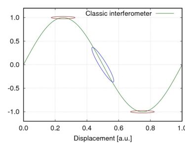
The optical response of a classic displacement measuring interferometer follows a sinusoidal shape. In the figure, a typical signal is shown. Signals of this kind can already be efficiently used if the total displacement is very limited so that there is the possibility to keep the working point of the interferometer fixed: In the region indicated with the blue ellipse, the change in signal with respect to a change in displacement is very high. On the other hand, it is close to zero in the area indicated with red ellipses. Thus, in the extrema of the sinusoid the sensitivity of the interferometer with respect to displacement is zero! Furthermore, the information of the direction of the displacement is lost.
Quadrature Detection: Generating two signals

To circumvent the aforementioned drawbacks of a classic interferometer, a technique called quadrature detection is available: Two signals are generated one of which is proportional to a sine function and the other to a cosine. This way, one obtains two signals in quadrature so that each time one of the signals is in an extremal point, the other one has its highest slope.
There are several technologies to obtain the quadrature signals including:
→ Obtaining phase shifted signals using polarization degrees of freedom
→ Sinusoidal wavelength modulation where the quadratures are revealed via spectral sidebands of the interferometer signal. This is the technology the PICOSCALE is based on.
Quadrature Detection: Lissajous graphs

When both quadrature signals are plotted against each other, one obtains a Lissajous graph. This is formed by a vector which moves on a circle. The angle of the vector gives the fraction of one interferometer fringe and by counting full revolutions, macroscopic motions are tracked. Additionally, the direction of motion is revealed. If the distance increases, the vector rotates clockwise, if the distance decreases, the vector rotates counter-clockwise.
In summary, quadrature detection allows to track macroscopic motions with microscopic resolution - including the direction.
Michelson Interferometer

A Michelson interferometer is probably the most popular interferometer architecture. A laser beam is split at a beam splitter into a reference and a measurement arm. Both partial beams are reflected at a reference and target mirror1, respectively, and recombine the beam splitter.
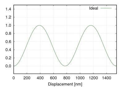
The recombined beams interfere and contain the information on the target’s position. The interferometer signal is an ideal sinusoid, even if there are losses in one of the two arms2. Quadrature detection gives a circle in the Lissajous graph.
1 In the PICOSCALE, the reference mirror can be directly coated to one of the surfaces of the beam splitter cube to obtain highest possible intrinsic stability.
2 Typical sources of losses are only partially reflecting targets or misaligned setups.
Fabry-Perot Interferometer
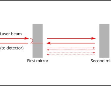
A Fabry-Perot interferometer is a very simple interferometer only consisting of two partially reflecting surfaces. The interfering beams of interest are given by
→ The beam that is directly reflected by the first mirror
→ The beam that transmits through the first mirror, reflects off the second mirror, and transmits trough the first mirror again
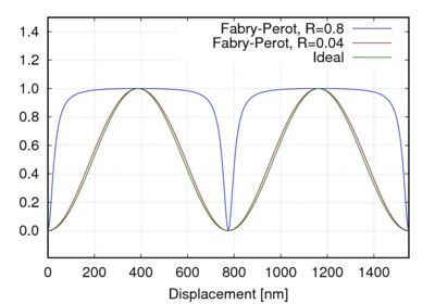
If the interferometer would only consist of these two beams, one would also obtain a perfect sinusoid. However, it is clear that the second beam also gets reflected off the first mirror again and performs an additional round trip which induces distortions.
Only for a very small parameter set, i.e. the reflectivities of the first and second mirror, the interferometer signal can be approximated as a sinusoid. Unfortunately, this set of parameters is given for very low reflectivity (single-digit %-range) so that care must be taken that no additional reflections can disturb the interferometer.
Lissajous Graphs and periodic nonlinearities
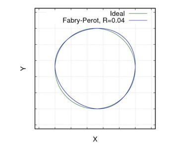
In the Lissajous graph of a non-perfect interferometer is compared to a perfect circle.
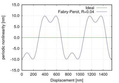
The deviations are clearly visible and would result in periodic nonlinearities in the order of +/- 10 nm. An ideal Michelson interferometer would not show these deviations.
Methods to optimize the accuracy
Even though the accuracy of displacement measurements can be at the single nanometer level with standard methods, high-precision applications require as high as possible accuracy. There are several methods to increase the accuracy:
Signal correction
→ There exist very robust and fast algorithms to properly scale and shift the Lissajous graph. This is necessary to account for different amplitudes and offsets of the quadrature signals
→ Both interferometer types, Michelson and Fabry-Perot benefit from these methods
Look-up table compensation
→ It is possible to measure the periodic nonlinearities and compensate them using look-up tables during the initialization process.
→ Dynamic updating look-up tables is very difficult; thus it can usually only be done in an initialization procedure and in Fabry-Perot interferometers it will not account for any changes in target reflectivity or misalignment during a measurement, as this changes the shape of the Lissajous graph, resulting in large periodic non-linearities. Re-initialization may become necessary.
→ In Michelson interferometers, the sources of periodic nonlinearities are of different origin and are typically much more deterministic and very insensitive to target misalignment or other changes in measurement conditions. Misalignment of the setup would only change the size of the Lissajous graph, not its shape. Signal correction will re-scale the Lissajous graph.